
Products on sale

ANSI B16.9 ASTM A403 WP321 SMLS WELDED Straight Reducing stainless steel tee equal 321 straight tees stainless steel tee
Related products

描述
ASME B16.9 Pipe End Caps and Butt Weld Elbow
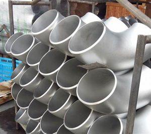
Fittings are important instruments that help join different piping systems together. Buttweld Fittings provide a unique way to join piping systems together. In this, fitting pieces of metal are placed over each other and welded. These fittings are unique because of the superior strength and excellent tolerances they exhibit in stress-induced environments. The Butt Weld Pipe Fittings provides options for manipulating the piping system in various directions or pressures. These fittings provide a leakproof and reliable piping connection. The Butt Weld Elbow is used to change the direction of flow of both fluids and gases in these systems. These elbows come in either short or long radius elbows. Their direction can be changed by 22.5, 45, 90, and 180 degrees. The Butt Weld 90 Elbow is known as a quarter bend elbow and is the most common elbow in the industry. These elbows possess superior tensile and yield strength. They allow for a smooth movement of flow through them. Reducing Elbow Buttweld are made up of openings of different sizes. This enables them to connect pipes of different sizes in a piping system.

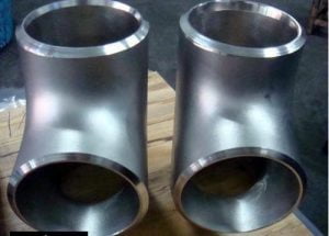
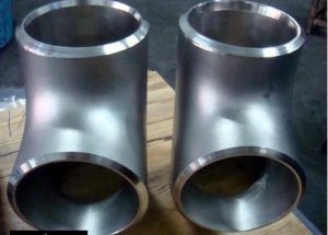
A Butt Weld Tee is a pipe fitting that has 3 openings. Each opening can connect pipes together. This is used to increase the flow of fluids and gases or divert the flow in different piping systems. This Tee Butt Weld helps in connecting the fitting to a stud or the divider. They are widely used in the transportation of potable water and firefighting systems. These tees are available either as equal or reducing tees. The Butt Weld Reducing Tee has an opening that is smaller in comparison to the other two openings. These tees are common components in vacuum cleaners. In the Butt Weld Reducer, different sizes of pipes can be installed. These reducers are also used in systems wherein the pressure is increased or decreased significantly. They are available as either concentric or eccentric reducers.
The Butt Weld Pipe Cap is used as a protective device on pipes, which protects them during transportation from falls. It also acts as a device to prevent the pipes from getting corroded due to moisture build-up. Butt Weld Cap can also help eliminate air blocks in pipelines. They are available in lengths up to 700mm. Our experience makes use of the latest technology and top-quality raw materials while producing all the products of the ASME B16.9 Buttwelded Fittings.
Buttweld Fittings Specification
| Standard Code | Standard Name |
| ASME B16.9 | Factory-made wrought steel butt-welding fittings |
| ASME B16.5 | Pipe flanges and flanged fittings |
| ASME B16.11 | Forged fittings socket-welding and threaded |
| ASME B16.47 | Steel flanges |
| ASME B16.28 | Wrought steel butt-welding short radius elbows and returns |
| MSS-SP-43 | Wrought stainless steel butt-welding fittings |
| MSS-SP-44 | Steel flanges |
| MSS-SP-75 | Specification for high test wrought butt welding fittings |
| MSS-SP-79 | Socket-welding reducer inserts |
| MSS-SP-83 | Class 3000 steel pipe unions socket-welding and threaded |
| MSS-SP-95 | Swage nipples and Circle plugs |
| MSS-SP-97 | Integrally reinforced forged branch outlet fittings-socket welding, threaded and butt-welding ends |
| ANSI/AWWA C207 | Steel Pipe Flanges For Waterworks Service |
| Elbows, seamless/ welded Type 2D, 3D, 5D | DIN EN 10253 Typ A/B | DIN 2605 part 1/2 |
| Tees, seamless / welded | DIN EN 10253 Typ A/B | DIN 2615 part 1/2 |
| Reducer, seamless / welded Concentric and eccentric | DIN EN 10253 Typ A/B | DIN 2616 Teil 1/2 |
| Caps | DIN EN 10253 Typ A/B | DIN 2617 |
Material of Buttweld Pipe Fittings
Butt Weld Pipe Fittings manufacturer in India, we use European/ German & Korean raw material to produce Butt Weld Reducing Tee and Cap
Nickel – Monel® – Inconel® – Incoloy® – Hastelloy® – Alloy 20 – Duplex
Nickel Alloy Butt Welding Fittings
ASTM / ASME SB 336 UNS 2200 ( NICKEL 200 ) , UNS 2201 (NICKEL 201 ) , UNS 4400 (MONEL 400 ) , UNS 8020 ( ALLOY 20 / 20 CB 3 ) , UNS 8825 INCONEL (825) , UNS 6600 (INCONEL 600 ) , UNS 6601 ( INCONEL 601 ) , UNS 6625 (INCONEL 625) , UNS 10276 ( HASTELLOY C 276 )
COPPER Alloy Steel Butt Welding Fittings
ASTM / ASME SB 111 UNS NO.C 10100 , C 10200 , C 10300 , C 10800 , C 12000, C 12200, C 70600 , C 71500
ASTM / ASME SB 466 UNS NO.C 70600 ( CU -NI- 90/10) , C 71500 ( CU -NI- 70/30)
Stainless Steel Butt Welding Fittings
ASTM / ASME SA 403 GR WP “S” / “W” / ” WX” 304 , 304L, 304H, 304N, 304LN, 309, 310H, 316, 316H, 317, 317L, 321, 321H, 347, 347 H
Duplex Steel Butt Welding Fittings
ASTM / ASME SA 815 UNS NO.S 31803, S 32205, S 32550, S 32750, S 32760
Carbon Steel Butt Welding Fittings
ASTM / ASME A 234 WPB, WPC
ASTM / ASME A 860 WPHY 42, WPHY 46, WPHY 52, WPH 60, WPHY 65 & WPHY 70
Alloy Steel Butt Welding Fittings
ASTM / ASME A 234 WP 1, WP 5, WP 9, WP 11, WP 12, WP 22, WP 23, WP 91
Manufacturing Buttweld Fittings
The most appropriate manufacturing method of a product will be decided with consideration of its material, sizes, shape, use, standards and other properties.
There are numerous processes for manufacturing Elbows alone, several examples listed as follows.
TEES: Hydraulic Bulge method (Cold Forming)
After cutting and placing raw material into a die, the pipe is pressed as hydraulic pressure pushes out the branch. The Tee is pressed against the die, leaving the finished product to have a truly smooth outer surface.

TEES: Extrusion method (Hot Forming)
Using raw material with a bigger diameter than the finished product, the branch outlet is extruded from pipe while the main body is being pressed. The outlet’s wall thickness can also be adjusted as needed. Applied to Tees with large diameters, heavy wall thickness and/or special material with challenging workability that cannot be manufactured using the hydraulic bulge method.
TEES: Steel Plate Welding method
Manufacturing methods for Elbows, using steel plates as the raw material. Includes UO-method, Monaka method and Throat-welding method.
UO method: After raw material plate is cut out into a specially designed shape, it is shaped first into an U-shape using a die, then the branch pipe is formed and then shaped into an O-shape (tubular form) using another die, finished with a single weld on the opposite side of the branch pipe. Usually applied to large diameter items used in severe conditions.
“Monaka” method: Two pieces of raw material plates cut out symmetrically are press formed and welded together. Usually applied to large-diameter items.
Throat-welding method: Mainly used for stainless and non-metal items, this method is similar to UO-method but with the weld on the same side as the branch pipe and the “branch throat.” Usually applied to low-pressure, corrosion-resistant items.
Material Grades of ASME B16.9 Butt welded Fittings
- St 37.0, S235
- St 35.8/I and III, P235GH TC1 and TC2
- C 22.8, H II, P265GH
- 15 Mo 3 (15 Mo 3 )
- 13 CrMo 45, 10 CrMo 9 10, 12 CrMo 19 5
- StE 290.7, L290NB, StE 360.7, L360NB
- W/TStE 355, P355QH1
- 1.4541, 1.4571, 1.4301, 1.4306, 1.4307, 1.4404, 1.4462 – Duplex , 1.4529, 1.4539, 1.4547, 1.4410 (Super-Duplex)
Butt Weld Reducing Tee Testing

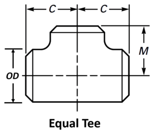
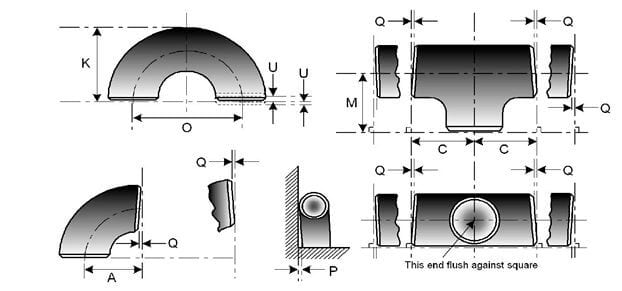
Pipe Tee dimensions are covered in ASME B16.9. Refer to the table given below for the size 1/2″ to 48″. In piping, two types of tees are used, straight or equal and reducing tee. The following shall be checked during the inspection of Pipe Tee Dimensions.
- The diameter of the branch and run pipe
- The thickness of the tee
- Center to center dimension for branch
- Length of the tee.
Straight / Equal Tee Dimensions
| Pipe Tee Dimensions As Per ASME B16.9 | ||||
| NOMINAL PIPE SIZE | OUTSIDE DIAMETER | CENTER TO END | LENGTH | |
|---|---|---|---|---|
| Inch. | OD | C | M | |
| 1/2 | 21.3 | 25 | 25 | |
| 3/4 | 26.7 | 29 | 29 | |
| 1 | 33.4 | 38 | 38 | |
| 1 1/4 | 42.2 | 48 | 48 | |
| 1 1/2 | 48.3 | 57 | 57 | |
| 2 | 60.3 | 64 | 64 | |
| 2 1/2 | 73 | 76 | 76 | |
| 3 | 88.9 | 86 | 86 | |
| 3 1/2 | 101.6 | 95 | 95 | |
| 4 | 114.3 | 105 | 105 | |
| 5 | 141.3 | 124 | 124 | |
| 6 | 168.3 | 143 | 143 | |
| 8 | 219.1 | 178 | 178 | |
| 10 | 273.1 | 216 | 216 | |
| 12 | 323.9 | 254 | 254 | |
| 14 | 355.6 | 279 | 279 | |
| 16 | 406.4 | 305 | 305 | |
| 18 | 457.2 | 343 | 343 | |
| 20 | 508 | 381 | 381 | |
| 22 | 559 | 419 | 419 | |
| 24 | 610 | 432 | 432 | |
| 26 | 660 | 495 | 495 | |
| 28 | 711 | 521 | 521 | |
| 30 | 762 | 559 | 559 | |
| 32 | 813 | 597 | 597 | |
| 34 | 864 | 635 | 635 | |
| 36 | 914 | 673 | 673 | |
| 38 | 965 | 711 | 711 | |
| 40 | 1016 | 749 | 749 | |
| 42 | 1067 | 762 | 711 | |
| 44 | 1118 | 813 | 762 | |
| 46 | 1168 | 851 | 800 | |
| 48 | 1219 | 889 | 838 | |
| All Dimensions are in mm | ||||
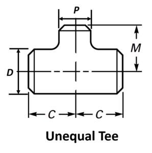
Reducing Tee Dimensions
| Pipe Tee Dimensions As Per ASME B16.9 | ||||
| NOMINAL PIPE SIZE | OUTSIDE DIAMETER | CENTER TO END | ||
|---|---|---|---|---|
| Inch | D | P | C | M |
| 1/2 x 3/8 | 21.3 | 17.1 | 25 | 25 |
| 1/2 x 1/4 | 21.3 | 13.7 | 25 | 25 |
| 3/4 x 1/2 | 26.7 | 21.3 | 29 | 29 |
| 3/4 x 3/8 | 26.7 | 17.1 | 29 | 29 |
| 1 x 3/4 | 33.4 | 26.7 | 38 | 38 |
| 1 x 1/2 | 33.4 | 21.3 | 38 | 38 |
| 1 1/4 x 1 | 42.2 | 33.4 | 48 | 48 |
| 1 1/4 x 3/4 | 42.2 | 26.7 | 48 | 48 |
| 1 1/4 x 1/2 | 42.2 | 21.3 | 48 | 48 |
| 1 1/2 x 1 1/2 | 48.3 | 42.2 | 57 | 57 |
| 1 1/2 x 1 | 48.3 | 33.4 | 57 | 57 |
| 1 1/2 x 3/4 | 48.3 | 26.7 | 57 | 57 |
| 1 1/2 x 1/2 | 48.3 | 21.3 | 57 | 57 |
| 2 x 1 1/2 | 60.3 | 48.2 | 64 | 60 |
| 2 x 1 1/4 | 60.3 | 42.2 | 64 | 57 |
| 2 x 1 | 60.3 | 33.4 | 64 | 51 |
| 2 x 3/4 | 60.3 | 26.7 | 64 | 44 |
| 2 1/2 x 2 | 73 | 60.3 | 76 | 70 |
| 2 1/2 x 1 1/2 | 73 | 48.3 | 76 | 67 |
| 2 1/2 x 1 1/4 | 73 | 42.2 | 76 | 64 |
| 2 1/2 x 1 | 73 | 33.4 | 76 | 57 |
| 3 x 2 1/2 | 88.9 | 73 | 86 | 83 |
| 3 x 2 | 88.9 | 60.3 | 86 | 76 |
| 3 x 1 1/2 | 88.9 | 48.3 | 86 | 73 |
| 3 x 1 1/4 | 88.9 | 42.2 | 86 | 70 |
| 3 1/2 x 3 | 101.6 | 88.9 | 95 | 92 |
| 3 1/2 x 21/2 | 101.6 | 73 | 95 | 89 |
| 3 1/2 x 2 | 101.6 | 60.3 | 95 | 83 |
| 3 1/2 x 1 1/2 | 101.6 | 48.3 | 95 | 79 |
| 4 x 3 1/2 | 114.3 | 101.6 | 105 | 102 |
| 4 x 3 | 114.3 | 88.9 | 105 | 98 |
| 4 x 2 1/2 | 114.3 | 73 | 105 | 95 |
| 4 x 2 | 114.3 | 60.3 | 105 | 89 |
| 4 x 1 1/2 | 114.3 | 48.3 | 105 | 86 |
| 5 x 4 | 141.3 | 114.3 | 124 | 117 |
| 5 x 3 1/2 | 141.3 | 101.6 | 124 | 114 |
| 5 x 3 | 141.3 | 88.9 | 124 | 111 |
| 5 x 2 1/2 | 141.3 | 73 | 124 | 108 |
| 5 x 2 | 141.3 | 60.3 | 124 | 105 |
| 6 x 5 | 168.3 | 141.3 | 143 | 137 |
| 6 x 4 | 168.3 | 114.3 | 143 | 130 |
| 6 x 3 1/2 | 168.3 | 101.6 | 143 | 127 |
| 6 x 3 | 168.3 | 88.9 | 143 | 124 |
| 6 x 2 1/2 | 168.3 | 73 | 143 | 121 |
| 8 x 6 | 219.1 | 168.3 | 178 | 168 |
| 8 x 5 | 219.1 | 141.3 | 178 | 162 |
| 8 x 4 | 219.1 | 114.3 | 178 | 156 |
| 8 x 3 1/2 | 219.1 | 101.6 | 178 | 152 |
| 10 x 8 | 273.1 | 219.1 | 216 | 203 |
| 10 x 6 | 273.1 | 168.1 | 216 | 194 |
| 10 x 5 | 273.1 | 141.3 | 216 | 191 |
| 10 x 4 | 273.1 | 114.3 | 216 | 184 |
| 12 x 10 | 323.9 | 273.1 | 254 | 241 |
| 12 x 8 | 323.9 | 219.1 | 254 | 229 |
| 12 x 6 | 323.9 | 168.3 | 254 | 219 |
| 12 x 5 | 323.9 | 141.3 | 254 | 216 |
| 14 x 12 | 355.6 | 323.9 | 279 | 270 |
| 14 x 10 | 355.6 | 273.1 | 279 | 257 |
| 14 x 8 | 355.6 | 219.1 | 279 | 248 |
| 14 x 6 | 355.6 | 168.3 | 279 | 238 |
| 16 x 14 | 406.4 | 355.6 | 305 | 305 |
| 16 x 12 | 406.4 | 323.9 | 305 | 295 |
| 16 x 10 | 406.4 | 273.1 | 305 | 283 |
| 16 x 8 | 406.4 | 219.1 | 305 | 273 |
| 16 x 6 | 406.4 | 168.3 | 305 | 264 |
| 18 x 16 | 457 | 406.4 | 343 | 330 |
| 18 x 14 | 457 | 355.6 | 343 | 330 |
| 18 x 12 | 457 | 323.9 | 343 | 321 |
| 18 x 10 | 457 | 273.1 | 343 | 308 |
| 18 x 8 | 457 | 219.1 | 343 | 298 |
| 20 x 18 | 508 | 457 | 381 | 368 |
| 20 x 16 | 508 | 406.4 | 381 | 356 |
| 20 x 14 | 508 | 355.6 | 381 | 356 |
| 20 x 12 | 508 | 323.9 | 381 | 346 |
| 20 x 10 | 508 | 273.1 | 381 | 333 |
| 20 x 8 | 508 | 219.1 | 381 | 324 |
| 22 x 20 | 559 | 508 | 419 | 406 |
| 22 x 18 | 559 | 457 | 419 | 394 |
| 22 x 16 | 559 | 406.4 | 419 | 381 |
| 22 x 14 | 559 | 355.6 | 419 | 381 |
| 22 x 12 | 559 | 323.9 | 419 | 371 |
| 24 x 10 | 559 | 273.1 | 419 | 359 |
| 24 x 22 | 610 | 559 | 432 | 432 |
| 24 x 20 | 610 | 508 | 432 | 432 |
| 24 x 18 | 610 | 457 | 432 | 419 |
| 24 x 16 | 610 | 406.4 | 432 | 406 |
| 24 x 14 | 610 | 355.6 | 432 | 406 |
| 24 x 12 | 610 | 323.9 | 432 | 397 |
| 24 x 10 | 610 | 273.1 | 432 | 384 |
| All Dimensions are in mm | ||||
Pipe FIttings Quiz – Test yourself, Take This Quiz
Pipe Fittings Dimensions Tolerance as per ASME B16.9
| NOMINAL PIPE SIZE | ALL FITTINGS | ALL FITTINGS | ALL FITTINGS | ELBOWS AND TEES | 180 DEG RETURN BENDS | 180 DEG RETURN BENDS | 180 DEG RETURN BENDS | REDUCERS | CAPS |
|---|---|---|---|---|---|---|---|---|---|
| NPS | O.D. at Bevel (1), (2) | I.D. at End (1), (3), (4) |
Wall Thickness (3) | Centre-to-End Dimension A,B,C,M | Centre-to-Centre O | Back-to-Face K | Alignment of Ends U | Overall Length H | Overall Length E |
| ½ to 2½ | 0.06 -0.03 |
0.03 | Not less than 87.5% of nominal thickness | 0.06 | 0.25 | 0.25 | 0.03 | 0.06 | 0.12 |
| 3 to 3 ½ | 0.06 | 0.06 | 0.06 | 0.25 | 0.25 | 0.03 | 0.06 | 0.12 | |
| 4 | 0.06 | 0.06 | 0.06 | 0.25 | 0.25 | 0.03 | 0.06 | 0.12 | |
| 5 to 8 | 0.09 -0.06 |
0.06 | 0.06 | 0.25 | 0.25 | 0.03 | 0.06 | 0.25 | |
| 10 to 18 | 0.16 -0.12 |
0.12 | 0.09 | 0.38 | 0.25 | 0.06 | 0.09 | 0.25 | |
| 20 to 24 | 0.25 -0.19 |
0.19 | 0.09 | 0.38 | 0.25 | 0.06 | 0.09 | 0.25 | |
| 26 to 30 | 0.25 -0.19 |
0.19 | 0.12 | … | … | … | 0.19 | 0.38 | |
| 32 to 48 | 0.25 -0.19 |
0.19 | 0.19 | … | … | … | 0.19 | 0.38 |
| NOMINAL PIPE SIZE NPS | ANGULARITY TOLERANCES | ANGULARITY TOLERANCES | ALL DIMENSIONS ARE GIVEN IN INCHES. TOLERANCES ARE EQUAL PLUS AND MINUS EXCEPT AS NOTED. |
|---|---|---|---|
| Off Angle Q | Off Plane P | (1) Out-of-round is the sum of absolute values of plus and minus tolerance. (2) This tolerance may not apply in localized areas of formed fittings where increased wall thickness is required to meet design requirements of ASME B16.9. (3) The inside diameter and the nominal wall thicknesses at ends are to be specified by the purchaser. (4) Unless otherwise specified by the purchaser, these tolerances apply to the nominal inside diameter, which equals the difference between the nominal outside diameter and twice the nominal wall thickness. |
|
| ½ to 4 | 0.03 | 0.06 | |
| 5 to 8 | 0.06 | 0.12 | |
| 10 to 12 | 0.09 | 0.19 | |
| 14 to 16 | 0.09 | 0.25 | |
| 18 to 24 | 0.12 | 0.38 | |
| 26 to 30 | 0.19 | 0.38 | |
| 32 to 42 | 0.19 | 0.50 | |
| 44 to 48 | 0.18 | 0.75 |
